The Build - Part 3
With the completion of the drilled and polished G10 board, the next step is the installation of the turrets. As you will recall, a turret is placed into a hole in the board. A special tool is put on the drill press and this is pressed into the turret in the board. As the drill press turns this attachment, an expansion of the base of the turret inside the board creates the gripping pressure to assure the turret is sturdily secured.
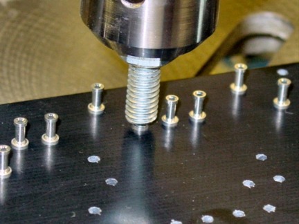
Turrets are seated into the board using this special attachment
This time-consuming process is continued until all of the turrets have been installed in the G10 board. Take a look at the top left corner of the completed turret board and you will see an angled cutout. Mikey did this to allow space for proper clearance of the CTS 10K bias pot that will be installed into the bottom of the chassis directly below this area.
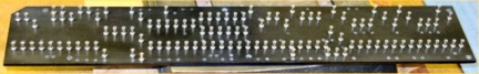
The finished G10 board with all of the turrets securely in place
With the turrets in place, the power rails and ground rails are installed. Mikey has come up with an innovative way of doing this instead of using the typical, un-insulated buss wire. The red and black wires in the picture look like separate pieces of Teflon stranded wire but they are not. Instead, he takes a single length of 18-gauge buss wire (the same kind soldered to the back of the pots) and runs one continuous piece to the power rail turrets and to the ground rail turrets.
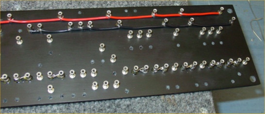
The power rail (red) and ground rail (black) buss wires are soldered to the turrets
Just before soldering these in place, Mikey removes the Teflon insulation from some 18-gauge stranded wire, cuts it to size and slides the Teflon shielding over the 18-gauge solid buss wire. In this close-up, you can see the how the continuous buss wire, wrapped in Teflon shield is wrapped around the turret and soldered. Also notice some of the turrets are wired together with thinner buss wire than what is used for the power and ground rails.
Having the turrets wired together performs the same function as hooking up two components to the same terminal, which will be done in a few places in this amp. It’s really the choice of the amp designer. Doing it this way keeps the components lined up nicely but it requires additional labor to install the extra turrets.
From this point, there is a fair amount of work that goes into putting the hookup wiring into the rest of the board. In order to minimize noise, Mikey runs the signal wires under the board, surfacing them right at their connection points. In the next photo, you can see the DRRI chassis with the pots and transformers installed, awaiting the completion of the main board.
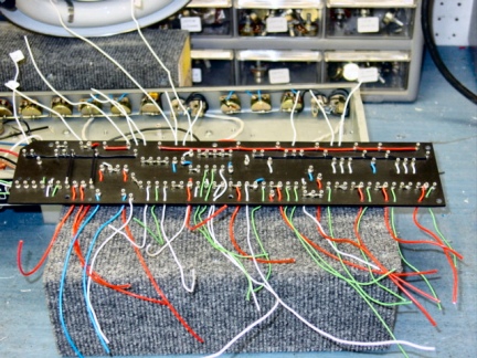
DRRI chassis (top) and main board with all hookup wires (below)
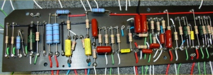
With the hookup wires in place, the next step is the installation of the components, primarily capacitors and resistors. In an earlier section I discussed the construction of capacitors. Remember, the function of capacitors is to restrict DC current and shape tone.
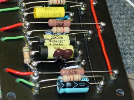
Capacitors and resistors in the Normal channel of the amplifier
The function of a resistor, as the name implies, is to provide a specific amount of opposition to current flowing through it. This causes a voltage drop, which the resistor does by radiating heat. This lets you control how much voltage you want to work with in various parts of the circuit. Resistors have a power rating that tells how much power/wattage (volts x current) they are capable of handling.
In the stock DRRI, some1/4-watt resistors are used, which Mikey feels are undersized. He uses 1-watt resistors throughout his circuits with the exception of a few 1/2-watt metal and carbon film resistors in non-critical sections. Of interest, the pots used to control the amp are just variable resistors. You can identify resistors very easily in the photos since they have bands of color, which are used to show the rating of the resistor measured in ohms. The rest of the components soldered to the turrets are capacitors, which come in a wide variety of colors, shapes and sizes.
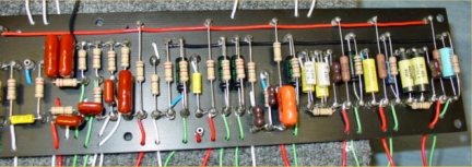
This next photo is of the “Vibrato” channel. For those of you that might not know, Fender created a lot of confusion by naming the second channels of their amps “Vibrato”, which is the modulation of pitch (like what a whammy bar on a guitar does). In fact, it is Tremolo, not Vibrato, which is produced by this part of the circuit. Tremolo modulates volume, not pitch. Fender knows better but they continue to use the word Vibrato on their amps so I have chosen to refer to this channel as Vibrato during this article because that is what it says on the faceplate of the DRRI.
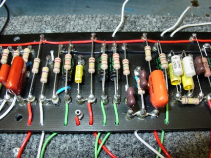
Capacitors and resistors in the "Vibrato" / Tremolo channel
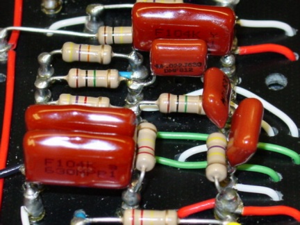
Close-up of capacitors (red), resistors (color banding) and wiringClose-up of capacitors (red), resistors (color banding) and wiring
As I examined the pictures Mikey was sending me of the building of the board, I could see the red wires were connected to the red power rail and the green wires were connected to the black ground rail. I assumed the white wires were signal wires (carrying the guitar signal) but I wasn’t sure about the blue wires so I asked Mikey. Here’s what he said:
“The red wires do go to the power rail and the plates of the preamp tubes. The greens do go to ground and go to the cathodes on the preamp tubes. The white wires are signal wires. On the bottom side of the board, they go to the grids of the preamp tubes and on top, they'll go to the pots. The blue wires run from the phase inverter to the power tubes so they're like signal wires. I just use blue to differentiate those, plus, I like blue!”
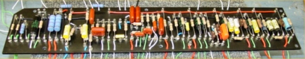
Fully completed main board with all components and hookup wires in place
Left side of completed main board
Right side of completed main board