The Build - Part 2
After the installation of the bias test points, the next step in the rebuild process is making an assembly for the pots and jacks. Since I’ve previously covered Mikey’s use of CTS and Alpha pots and Switchcraft jacks, I’ll jump right to the construction. Here’s a photo from the first batch of pictures I received from Mikey on this part of the rebuild.
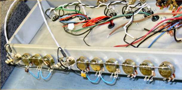
There’s a funny story that goes along with this picture. One night at about 3:00 am, I got up for a drink of water and decided to check my email. Mikey must have been working late that evening because I’d received a new batch of pictures. When I opened the email and saw this picture I knew something wasn’t right. Why were the jacks and pots on the outside of the chassis? Why were they upside down? What happened to the black faceplate? Was I losing my mind or was something else going on? I emailed Mikey looking for answers. Here’s what he wrote back.
“Hey Wayne! No, you're not crazy. You were just half asleep and you were looking for something that wasn't there! I took the faceplate off after I enlarged the holes. The faceplate has to be on when enlarging the holes for the CTS pots and input jack insulators so the faceplate holes will be enlarged as well. Then, I take the faceplate off and store it safely somewhere else while I'm working on the pot buss assembly. The faceplate is held on the chassis by the pot nuts, input jack nuts and the pilot light assembly. It's just a piece of metal with holes in it. When the pots and input jacks are put through the holes, and the nuts are attached and tightened, that's what holds the faceplate on.”
“I temporarily mount the pots on the outside of the chassis, upside down. This gives me a better work angle, plus, when I solder the buss wire to the back of the pots, the pots turn out perfectly spaced, since I'm soldering the buss wire with the pots in their correct holes. When completed, I unscrew the pots from inside, lift the assembly and just put it back through the holes from the inside of the chassis. Now, the pots are right side up, the spacing is perfect, and life, as we know it, is good!"
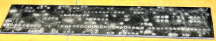
Whew. I felt better after hearing this! My brain was still intact and I was curious about the “buss wire” he mentioned. You can see it in the pictures. It is the silver, unshielded wire connecting across the backs of all of the pots. It is used to ground the pots, which are part of the preamp section. Here’s a close-up shot.
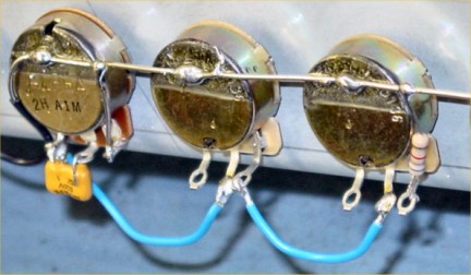
Buss wire soldered to the backs of the pots
Soldering the buss wire to the pots isn’t as easy as you might think. Mikey explained he uses a 100 watt soldering iron to heat up the area enough to make sure to get a nice even bead over the buss wire. This buss wire and other grounds from the preamp section are kept separate from the grounding of the power amp section. Since the input jacks are isolated from the chassis by the insulating shoulder washers, the input jacks can be grounded to the same ground used for this buss wire.
If you look carefully, you can see that Mikey uses twisted pair, insulated Teflon wire for the input jacks (the white wire on the right). In addition to the two wires from this twisted pair, there is also a metal-mesh shield inside the Teflon outer shell. Mikey attaches a black grounding wire to this shield. It is wired to the appropriate parts of the input jacks to keep hum and noise from entering the input wires.
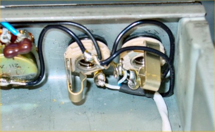
Input jacks for the Normal channel
You can see the black grounding wire going from the input jack over to the beginning of the buss wire on the back of the pot, grounding the jacks and the Teflon input wire. The other end of the white Teflon wire will go to 68K resistors, which will be attached directly to the input grid of the preamp tubes. By the way, did you notice the pots and jacks are back inside the chassis where they belong :>)
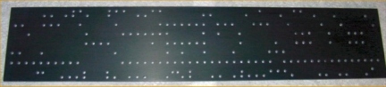
Next up is the creation of the main circuit board that will house the majority of the resistors and capacitors used in various stages of the amp. Before doing this article, I had no idea how much work goes into the creation of a custom turret board. Of course, the most critical part is getting the circuit design done correctly. With all of the optional mods I’ve selected and the enhancements Mikey has added since the rebuild of his personal DRRI, there are quite a few circuit changes. For this step in the process, the design changes are added to the existing design template.
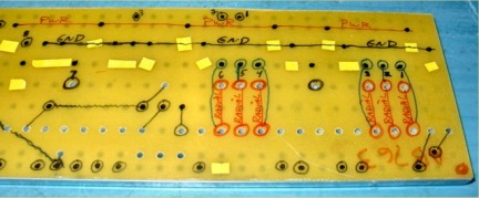
Custom turret board template showing many design changes
Then, the 1/8” G10 board is cut to size from a larger piece of G10 material and the edges are sanded smooth.
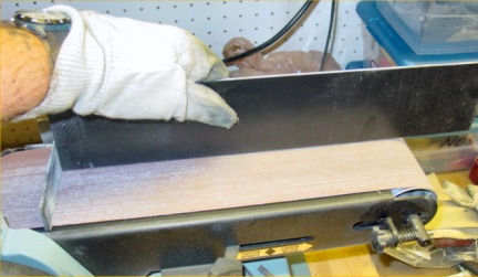
Sanding the edges of the newly-cut G10 board
Here’s a photo of the three items needed to create the custom turret board.
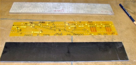
G10 board (bottom), circuit template, metal drill jig (top)
The G10 board is placed on the drill press; the metal drill jig is placed on top of it, followed by the circuit template. This is all well secured to the drill press in preparation for the actual drilling. Wherever there is an open hole or an indicated spot for a new hole on the template, a hole needs drilled through the G10 board. The jig provides a secure path for the drill bit so the holes are cut cleanly on the board. It is time consuming to drill all of these holes.
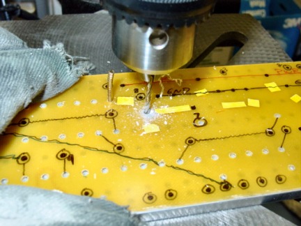
Drilling the G10 board (underneath and out of site) through the template and metal jig
Completed G10 board just after removal from the drill press
Once the drilling of the board is complete, Mikey sands and polishes it. This is the last step of the board preparation before the installation of the turrets and board components.