More Design Details
In the last section I talked about 6V6 tubes for power amplification. I thought you’d enjoy seeing this photo of two 6V6 tubes; the type of power tube used in Deluxe Reverb amps. These particular 6V6's are some of the best ones ever manufactured. They were made in 1951 for the French military. NOS means they were sold as New Old Stock (never used).
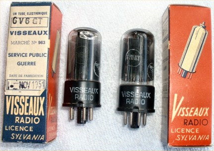
They are also NIB, which means they are essentially New In the Box. These are beautiful sounding tubes that compare favorably with the famous RCA blackplate 6V6’s. For new tube manufacturers of 6V6 tubes, I like JJ Electronic and Electro-Harmonix.
One of the things I don’t like having to do is to take my amp to a tech for biasing when changing power tubes. The DRRI has a bias adjustment on the bottom of the chassis, which is a good quality CTS 10K bias pot so Mikey reuses this part in the rebuild. As I mentioned, Mikey is adding an optional mod to my amp so that I can bias it myself without opening up the amp and exposing myself to lethal charges or having to buy an external bias probe. Mikey solves this by adding three test points on the back of the chassis so I can set my own bias with a voltmeter using the cathode resistor method.
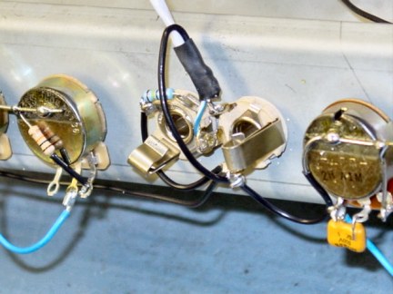
CTS pot (left), Switchcraft jacks, Alpha pot (right)
The way this works is a 1-ohm 1% resistor is placed between ground and pin 8 on the power tubes. When you plug a voltmeter into the test jacks, it’ll measure the voltage drop across the resistor. When I pick up my amp from Mikey, we’ll play with the bias on the tubes to find the spot that sounds best for me and is within the operating parameters of the 6V6 tubes. When it is time to replace my power tubes, I’ll buy a matched pair and then re-bias the amp to these same settings. This is really a nice way to make the amp user-friendly.
Mikey and I had been knee-deep-in-the-hoopla for 3.5 hours and we decided it was time for a break. We went to the kitchen and got a couple of Cokes, ice and glasses and sat outside to relax a bit. I continued to ask Mikey about the technical details of the rebuild and about tube amp electronics.
Mikey told of his time in the military and his assignment in Alaska where he played concerts with his band. At one big concert, he played to a huge crowd sharing the bill with Little Feat, Tower of Power, W.P. Brennan from Australia and 14 other local bands. It was like a mini Woodstock and it sure sounds like it was a lot of fun. After this brief respite, we returned to the shop and picked up where we’d left off.
Next up was a discussion of the typical negative feedback loop (NFB) used in the Deluxe Reverb and the tweaking Mikey has done to get the best response out of it. I learned that a global NFB loop is created by taking the signal from the output transformer at the positive terminal of the speaker jack and sending it back through a resistor to the phase inverter, which is at point earlier in the circuit before the power tubes. It is called negative feedback because this output signal is 180 degrees out of phase with the input signal.
Mikey experimented for a long time to find just the right resistor so that it wouldn’t mess with the clean sounds except making them a bit fatter with more harmonics. It also helps the tone when the amp is pushed hard, giving the amp more gain and girth. I was to experience this later when we started trying out the amps. Here’s what Mikey had to say about his modification to the NFB loop.
“This acts like a fixed Presence/Resonance control. Presence usually only allows the higher frequencies to pass through without going through the NFB circuit, and Resonance usually lets the lower frequencies through without going through NFB. The resistor mod that I'm using works with all of the frequencies, it doesn't only pass either high or low frequencies. It restricts the amount of signal that goes through the NFB circuit so that it leaves a portion of all of the frequencies to be reproduced naturally, without NFB. NFB reduces distortion and makes for a cleaner tone. Since a portion of the tones aren't going through the NFB circuit, they're reproduced fully, with more harmonics and Phatness!”
Regarding the phase inverter (PI), Mikey does some mods to this circuit too. This includes putting in a very high-quality coupling cap leading to the PI because all of the signal from the entire preamp section, reverb and tremolo pass through it on the way to the phase inverter. The PI caps themselves are also of high-quality. Here’s what Mikey has to say about his changes to the phase inverter circuit.
“The PI caps were modified to prevent the "farting" when playing at high volume. The PI coupling cap was actually raised a bit, to compensate a little for the PI cap change, and to let some more midrange/fullness through from the preamp circuit to the PI. My philosophy is that it's better to make several smaller changes/mods throughout the entire circuit than to just make one large/huge change and throw everything else off. Where I make one change, I usually try to make another small compensating change somewhere else in the circuit.”
Another enhancement Mikey makes from the stock DRRI is that he removes the Fender pots and jacks attached to the PCB and replaces them with new pots and jacks; wiring them directly to the appropriate parts of the circuit. He uses CTS and Alpha pots and Switchcraft jacks.
The Alpha pots fit the existing holes but in order to use CTS pots, the holes must be enlarged. To do this, Mikey uses UniBits (step drill bits). His design calls for using shoulder washers to insulate the input jacks from the chassis to help keep the amp quiet. The input jack holes have to be enlarged to 1/2“ to accommodate the insulating shoulder washers.
Mikey puts the Normal channel in phase with the Vibrato channel. If this isn’t done and you try to play the amp when using both channels simultaneously, the sound is really puny since they are out of phase. This mod also has the advantage of routing the Normal channel through the tremolo and reverb circuits, which isn’t normally available on a Deluxe Reverb. The Normal channel is also modified to give Marshallesque tone and gain. He explained his goal is to add an extra midrange emphasis and allow the circuit to overdrive sooner.
During our conversation, I became curious about the use of different types of capacitors and how they are used to modify tone. Mikey explained to me how a capacitor works and showed me examples of “film and foil” caps and “metallized” caps. He had a couple of them disassembled and he used them to help me understand how caps are constructed.
I now know that film and foil caps use two strips of film and two strips of foil, with a set of film and foil strips creating one “layer”. Metallized caps have two strips, each with an aluminum conductor atomized and vapor deposited on dielectric film. In both cases, the two layers are rolled up together so there is an anode conductor and a cathode conductor separated by a layer of film.
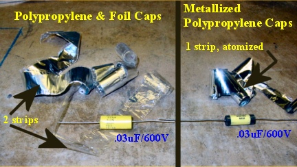
Two different methods of construction are evident in these two types of capacitors
Film and foil caps are much bigger than metallized caps. You can see this in the picture above. Both caps have the same .03uF/600V rating, but the polypropylene and foil cap is much larger/rounder than the metallized polypropylene cap on the right. On the left, the metal foil is less shiny and crinkled looking when unraveled. On the right, the metal looks very shiny and smooth since the metal was sprayed directly on to the dielectric (the polypropylene film).
The way a capacitor works is when power is applied from the positive and negative wires from the power supply, it becomes charged (one of the layers becomes positive and the other negative). Even with the power supply disconnected, the capacitor will continue to hold a charge. How much of a charge it can hold is measured in Farads (F). Another measure is the voltage rating, which tells you how much DC current the capacitor will block. In the above photo, the capacitors are rated at .03 microfarads and 600 volts.
While capacitors will block DC current, they will allow AC current to “flow” through. In actuality, capacitors cycle through charges and discharges somewhat like a very fast, rechargeable battery, which appears to be a flow of AC current. Interestingly, this cycling happens to let high frequencies pass through more easily than low frequencies. This means that capacitors can be used to shape tone in addition to passing an AC signal from one circuit to another without letting any DC current to get through.
There are many types of materials used for cap construction but polypropylene and polyester (foil or metallized) are the most common. Other examples of capacitor construction are paper/oil, polystyrene, polycarbonate, mica and ceramic. Mikey had this to offer on his choice of capacitors (note the preparation he did for my visit based on our voice and email correspondence).
“I generally prefer polyester caps overall as they give off a "warmer" tone/more midrange, which is especially nice in a bright Fender circuit. But I changed the caps in my amp for your demo and used polypropylene Orange Drops for the PI caps and PI coupling cap. I also used them in the normal channel tone stack and a couple of other places since you like a brighter tone. Polypropylene gives off more highs and more lows to my ears. Those were polypropylene/foil caps, 716P's. Polyester, either metallized or foil, tends to give more mids and upper mids.”
Mikey explained a technique he will to use for the building of my amp. He calls it “Cap Stacking”, which is the use of a combination of caps of different types wired together to get the tone and grit characteristics to best fit his redesigned circuit and my particular tone preferences. I really enjoyed this part of the discussion and learned a lot I didn’t know about caps. As you can see, there’s a lot of attention to detail that goes into the design of Mikey’s amps.
There is an option Mikey uses that I did not select. On his amp, Mikey added a pot on the back of the chassis to the Normal channel to have variable control of the midrange EQ. This lets you dial-in just the right amount of mids for your particular guitar and for the sound you are going for. Mikey installed this extra pot in place of the extension speaker jack. Since I sometimes like to use a Celestion Alnico Blue extension speaker, Mikey said that when we try out his amp, I can find the sweet spot of the mids on his amp that best suits my taste preference. He’ll measure the resistance of the pot at that setting and just build it into the circuit of the Normal channel, leaving the extension speaker jack available.
The tremolo circuit is different from the stock DRRI circuit. His tremolo circuit uses the bias to pulsate the power tubes to generate a smooth tremolo effect rather than the on/off type found in the DRRI, which uses an optoisolator. He also slows down the tremolo circuit and raises the intensity a bit to get the most pleasing sound.
The reverb circuit is also significantly different from stock in several ways. The DRRI uses lower quality, PCB housed RCA jacks, which Mikey replaces with heavy-duty RCA female jacks affixed directly to the chassis. To do this, another hole has to be drilled in the chassis but the quality is worth it. I chose the option to use a high-quality Mercury reverb transformer. As anyone that uses a Fender amp with reverb knows, if you turn the reverb knob up past 2, it gets pretty boingy and surf-like. This is because of the use of a linear pot on the stock DRRI. Mikey uses an audio pot for this application so the user can have finer control of the reverb by allowing more incremental changes. Here’s Mikey’s explanation to me of the differences between linear and audio pots.
“Linear pots are the same price as audio pots. It's in the way that the pots function that makes the difference. The resistance of a linear pot is, well, linear! It's in equal increments. For example, if you have a 100K linear pot, and you turn the knob to the halfway point, the resistance will be 50K. An audio pot functions differently, but it functions closer to the way that our ears hear. For the same 100K pot, the halfway point may only represent about 20% of the total resistance, or about 20K.”
“As the knob rotates, the resistance goes up more, then finally arrives at the same 100K total resistance value. But, it's that first half of the audio pot that gives us finer control, to get those "in-between" values, and again, human ears "hear" in audio fashion, not linear. That's one of the reasons that on the Fender reverbs that use linear pots, it sounds like it's "all on" even when the knob is only on 2 or 3. An audio pot would be halfway up approximately to get that same level.”
“On some of the less expensive amps, some makers use linear pots on their volume controls so the customer thinks the amp is "loud". Imagine being in a store and trying out an amp, turning the volume up to 2 and blasting out the store. The customer would think that this was one loud amp, but the linear pot makes the ears think that the amp is loud when it's just giving more volume upfront due to the nature of the linear pot. With an audio pot, the volume control may have to be up around halfway to get the same perceived volume.”
We finally finished going through the various parts of the amp and all of my questions had been answered. At this point, Mikey and I had been talking for about 5.5 hours and we hadn’t played a note yet. It was time to change that!