Bias Test Points
As previously mentioned, I elected to get the “bias test points” optional mod from Mikey. This does cost more but it is worth it to me. Having bias test points will let me replace the 6V6 power tubes myself using just a voltmeter or multimeter.
Finding the right spot to place the test points in the amp without interfering with the back of the chassis is tricky. Mikey told me he was constrained by the slanted part of the back panel where it presses up against the back of the chassis as well as the rectifier socket on the inside of the amp. You can see an angled pencil mark indicating where the back panel lays across the rear of the chassis. On the inside of the chassis, there had to be room to fit the resistors between the red test points and the ground test point. As previously mentioned, I elected to get the “bias test points” optional mod from Mikey. This does cost more but it is worth it to me. Having bias test points will let me replace the 6V6 power tubes myself using just a voltmeter or multimeter.
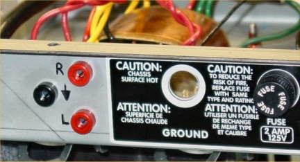
Ground (black) and right and left (red) power tube test points
Finding the right spot to place the test points in the amp without interfering with the back of the chassis is tricky. Mikey told me he was constrained by the slanted part of the back panel where it presses up against the back of the chassis as well as the rectifier socket on the inside of the amp. You can see an angled pencil mark indicating where the back panel lays across the rear of the chassis. On the inside of the chassis, there had to be room to fit the resistors between the red test points and the ground test point.
In the next two photos, you can see that the bias test points are right near the rectifier tube socket. So as to avoid any problems, Mikey moved the B+ wire (red wire) from the pin on the rectifier socket so that it moves away from the bias resistors and runs along the bend of the chassis to the standby switch. It's out of the way of everything else.
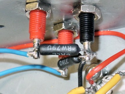
Internal wiring of the bias test points. 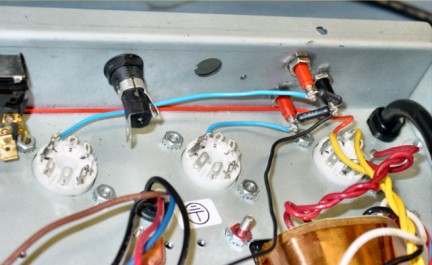
Light blue wires attach at pin 8 of the white power tube sockets, then to the red bias test points
The way the bias test points work is pin 8 of each power tube is wired to a red terminal on the inside of the bias test points. Each red terminal has a 1-ohm 1% resistor that goes to the black terminal, which is then wired to ground at one of the power transformer mounting bolts. Without bias test points, pin 8 is just wired to ground but adding this resistor allows a bias measurement in millivolts across the resistor, which converts directly to milliamps of current draw in the tube due to Ohm’s law.
Although I’m jumping ahead of the construction process, the next picture shows the bias circuit portion of the main board created in “The Build – Part 3”. In the picture you can see the bias resistor, bias diode, bias capacitor and bias tap resistors, which create an "artificial" center tap from the power transformer.
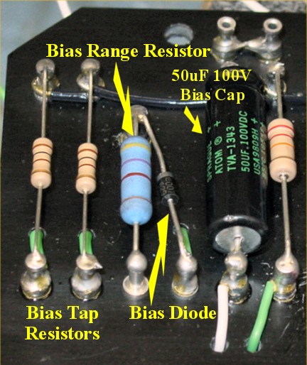
Bias circuit on the main board
The way this part of the circuit works is AC voltage from the power transformer enters the bias range resistor, which drops the voltage before entering the bias diode. The bias diode rectifies the AC voltage into DC negative voltage, much like the5AR4 tube does in the power section of the amp. This fluctuating DC voltage gets smoothed out by the bias capacitor on its way to the bias pot.
The whole purpose of biasing is to set the right amount of current passing through the power tubes when no signal is present. Think of this as setting the idle on a car. If there’s not enough current, the tubes will sound sterile and won’t perform properly, and if there is too much current, the tubes will run too hot and there will be unwanted distortion and a good chance of tube failure.
The bias control on the bottom of the chassis is turned while looking at readings on the voltmeter, which has probes inserted into the bias test points. In the next photo, you can see the bias adjustment pot. Note that a screwdriver is placed in the white slot in the middle of the pot to turn it.
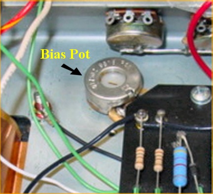
Bias adjustment pot as it looks from inside the chassis
As you can see, the bias pot can be turned from inside the chassis. What you can’t see is this adjustment can also be made from the bottom of the chassis without taking the chassis out of the cabinet. A screwdriver is simply inserted into a hole in the bottom of the chassis leading to this pot and the adjustment is made while watching a voltmeter attached to the bias test points, which are also on the outside of the chassis. Hooray. No lethal charges to fry guitar players!
The voltage coming out of the bias pot goes to a junction with two resistors, which sends the right amount of separate negative voltage to the grids of each of the 6V6 power tubes. This negative voltage determines how much current goes through the tubes when they are at idle.
The bias is set to make sure the proper plate dissipation rating (in watts) of the output tubes is reached. The maximum plate dissipation rating for a single 6V6 tube is about 14 watts. Since it is best to operate at about 70% of maximum plate dissipation, the bias is adjusted to bring the plate dissipation down to about 10 watts (.7 * 14 = 9.8). The calculation of the proper bias setting is done like this:
The formula to calculate plate dissipation says that P = E * I, which means that Power (watts) = Volts * Current Draw (amperes). Let’s say the plate voltage is 400V. The current draw (the unknown variable we need for setting the bias) can be calculated like this:
P = E * I
10 = 400 * I
10/400 = I
.025 = I (amperes)
In this example, since .025 amperes = 25ma (milliamps), and because of the 1-ohm 1% resistor, the bias setting for a power tube will be right when the voltmeter reads 25mv. The next time I put in a set of matched power tubes, I would just set the bias to 25mv.
When I pick up my amp, Mikey will measure the actual plate voltage (it probably isn’t exactly 400) and we’ll play with the bias to find my favorite bias setting that puts each tube close to10 watts. Since the amp uses two 6V6 tubes in class AB (push/pull), the output of the amp will be about 20 watts, which in my opinion is just about the right amount of power for most gigs in smaller rooms.
![]()