The Build - Part 4
Now that the components and hookup wires are
installed on
the main board, it is placed inside the chassis.

DRRI chassis with the main board installed
Here’s a close-up of part of the chassis interior with some features of the amp highlighte DRRI chassis with the main board installed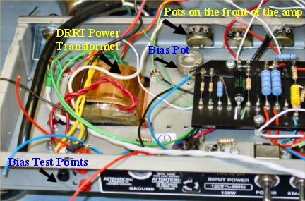
Close-up of the interior during the later stages of assembly. Note the soon-to-be-replaced DRRI power transformer
The phase inverter (also known as a phase inverter splitter) is a very important circuit in the amp. The input from all of the previous sections goes through a mixing resistor and then to a coupling capacitor that links this mixed signal to the phase inverter (PI). The phase inverter circuit, made up of resistors, capacitors and a 12AT7 tube take the incoming signal, split it in two, and then changes one of the signals to be 180 degrees out of phase with the other.
The idea is to have one of the 6V6 power tubes amplify one half of the sine wave of the incoming signal and the other 6V6 amplify the opposite half of the signal. This is known as running the power tubes in push-pull mode, which is also called Class AB. While one tube is amplifying its part of the sine wave, the other tube rests. Class AB operation is able to generate more power out of the two tubes than if they were both running all the time, which is called Class A. Here’s what the phase inverter section of the main board looks like.
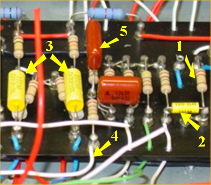
Layout of the phase inverter and NFB loop on the main board
1. The blue wire to the top right of this resistor brings the signal from all previous circuits in the amp into what is called “the mixing resistor".
2. This passes through the coupling capacitor (.002uF Mallory metallized polyester) into resistors and capacitors in the phase inverter circuit.
3. The two big, yellow capacitors (and two caps hidden underneath them – Cap Stacking) handle the split signals. They each connect to the plates of the 12AT7 phase inverter tube via red wires, which can’t be seen here but they are visible in the next photo. The blue wires at the bottom of this photo connect to pin 6 of the power tubes, which is connected to pin 5 (input/grid) via a 1.5K swamp resistor.
4. Negative Feedback Loop (NFB). After the phase inverter tube, the 6V6 power tubes amplify each half of the sine wave and send the amplified signal to the output transformer to drive the speaker. The white wire (#4) is coming back from the positive terminal of the speaker output jack into two resistors that feed a part of the output voltage back into the phase inverter.
5. Take a look at the red capacitor on top of the resistor (#5). This cap acts like a fixed presence control in the NFB circuit. (Note that in my third visit to Mikey, this cap was removed. Ultimately, it had made the amp too bright overall.)
Whew. That’s a lot to think about! It took me awhile to understand how the phase inverter and negative feedback circuits work. I spent about an hour on the phone talking with Mikey about these circuits and why he chose the specific types of resistors and capacitors used here. I also went to my bookshelf and looked up these circuits in a couple of my tube amplifier books to make sure I could explain it reasonably well. While I’m thinking of books, you might like to know about the books and videos I have in my library to help me with my hobby. You can find the whole list in the “Contact Information” section of this article.
Let’s take a moment to diverge from the technical discussion so I can share some of Mikey’s philosophy on choosing various components and circuit modifications in an amp. He told me on the phone he views it much like cooking. You start with a good base (like the AB763 circuit in the Deluxe Reverb) and add a pinch of this and a dash of that to bring out complexity and character in an amp. Just as one might add lemon to a sauce to balance out the sugar, Mikey says he likes to make subtle tweaks to guide the amp to the desired sonic result.
Going back to the technical stuff, this “amp cooking” is very evident in the phase inverter and negative feedback sections mentioned above. Take for example the coupling cap after the mixing resistor. The standard capacitor used here in the DRRI is .001uF, which is one of the reasons the stock amp is very bright.
In Mikey’s personal amp, he changed this to a .0047 capacitor, which is about 5X more than stock. This emphasizes the mids and upper mids, adding some phatness to the tone, which works great with Mikey’s G&L ASAT guitar. But since I expressed interest in a brighter sound from the amp on the Vibrato channel, Mikey has put a .002 metallized polyester coupling cap in my amp, allowing it to be brighter than his amp while giving more of the upper mids than the stock DRRI.
But just like adding lemon to balance sugar, Mikey wants to make sure there is enough brightness in the amp for my tastes so further modifications are made in the PI circuit. For example in my amp, the two big yellow caps (#3) are Mallory-150 .047 metallized polyester caps for a smooth tone but he has used his Cap Stacking method to add two .01uF metallized polypropylene caps (white) right underneath them. Together, they have a rating of .057uF.
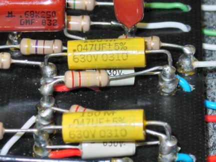
Cap Stacking using .047uF caps (top - yellow) and .01uF caps (bottom - white)
Metallized polypropylene caps (bottom – white) tend to bring out some brightness. This should help balance the .002uF coupling cap to help me get the brightness I’m looking for. Another tweak to the recipe that Mikey is using is the placement of a capacitor in the negative feedback loop (#5), which acts as a fixed presence control to help give some sizzle in the top end of the tone.
The goal is to have an even response in the lows, mids and highs with a bit of personalization for the player. As you can see, a pinch of this and a dash of that make for a tasty dish, personally tweaked to my sonic preferences. Can you dig it? I can!
There are only a couple of items to finish on the build. All the remaining hookup wires are connected to the pots, jacks and switches. The Triode/Pentode switch gets installed and all of the tubes must be powered using filament wire. If you glance back at the pentode circuit diagram in the “Design Details” section, you can appreciate that the filament wires are connected to the cathodes of every tube. This heats up the cathodes so they start emitting electrons.Metallized polypropylene caps (bottom – white) tend to bring out some brightness. This should help balance the .002uF coupling cap to help me get the brightness I’m looking for. Another tweak to the recipe that Mikey is using is the placement of a capacitor in the negative feedback loop (#5), which acts as a fixed presence control to help give some sizzle in the top end of the tone.
The goal is to have an even response in the lows, mids and highs with a bit of personalization for the player. As you can see, a pinch of this and a dash of that make for a tasty dish, personally tweaked to my sonic preferences. Can you dig it? I can!
There are only a couple of items to finish on the build. All the remaining hookup wires are connected to the pots, jacks and switches. The Triode/Pentode switch gets installed and all of the tubes must be powered using filament wire. If you glance back at the pentode circuit diagram in the “Design Details” section, you can appreciate that the filament wires are connected to the cathodes of every tube. This heats up the cathodes so they start emitting electrons.
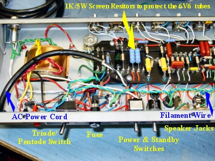
Completed connections on the almost-finished chassis
Take special note of the large, blue resistors between the bias circuit and the phase inverter circuit on the board. These are the 1K/5W screen resistors used to protect the 6V6 powers tubes. This is how this whole project started in the first place! The 470-ohm/1-watt screen resistors kept burning up when a 6V6 tube failed. Now, if a 6V6 tube fails at the screen grid, these 1000-ohm/5-watt resistors will remain intact and I shouldn’t need to have the amp serviced. I can just pop in a new matched pair of tubes and set the bias using the new test points.
I find it amusing my initial desire to replace these two weak components has led me along the path of getting this entire amp rebuilt :>)